
What is the required power supply for a sensor with integrated amplifier that provides a 4-20 mA (2-wires) signal?
Answer:
The particularity of the power supply for sensors equipped with a 4-20mA (2-wires) amplifier (Option C or C6) is that it depends on the value of the load resistance of the reading instrument (RL) increased by the resistance of the wiring (RW).
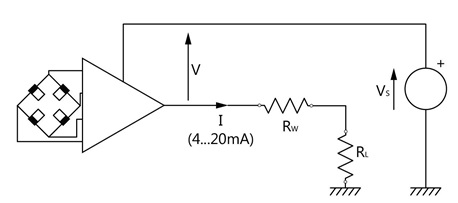
Indeed, for a correct operation, the power supplyat the terminals of the amplifier (V) must be at least 9 to 28VDC. However V = VS - I x (RL + RW) with I being able to reach 20 mA.
Consequently, Vs must be greater than or equal to 9 + (RL + RW) x 0.02.
Examples:
- Input resistance of the reading device RL: 33 Ohms Wiring resistance Rw: 4 Ohm. To be able to generate a 20mA signal, the supply voltage must be at least: 9V + ((33+4)*0.02) = 9.74V
2. With RL + RW = 1 kΩ (abnormally high value), VS must be at least: 9 + 20 = 29 V to be able to generate a 20mA signal with the specified linearity.
Likewise, for a specified supply voltage, the value of the sum of the load resistors will be limited to (VS - 9) / 0.02.
Example: With VS = 24 V, the value of RL + RW may not exceed 750 Ω in order to generate a 20mA signal with the specified linearity.